
Summary
Ground-penetrating radar records a reflected signal after a journey out and back. Turning that travel time into a depth requires a propagation velocity and an appropriate interpretation of the path. A time value alone is neither a depth measurement nor permission to cut.
For related work, see Sirius Concrete Cutters’ concrete scanning service.
A returning signal has travelled twice
An echo arrives after sound has travelled to a reflecting surface and back to the listener. Radar is an electromagnetic process rather than a sound wave, but the journey provides a useful starting analogy. A reflected radar signal also takes time to travel away from an antenna and return. The elapsed time belongs to that complete trip.
If the journey follows a simple straight line down to a reflector and back along the same line, its total length is twice the one-way distance. Forgetting the return leg would confuse the complete path with the depth beneath the surface. This factor of two is a matter of geometry, before any particular concrete value or instrument setting is considered.
Time and distance use different units
A clock records elapsed time. A ruler records length. They cannot be equated without another piece of information connecting them. For uniform motion, distance is speed multiplied by time. The speed tells us how much distance is covered in each unit of time. Without it, a time value describes duration but leaves distance undetermined.
Imagine two signals taking the same elapsed time through two different idealised materials. If one travels faster, it covers more distance during that time. The equal times therefore do not require equal path lengths. Conversely, two equal paths can have different travel times when the propagation velocities differ.
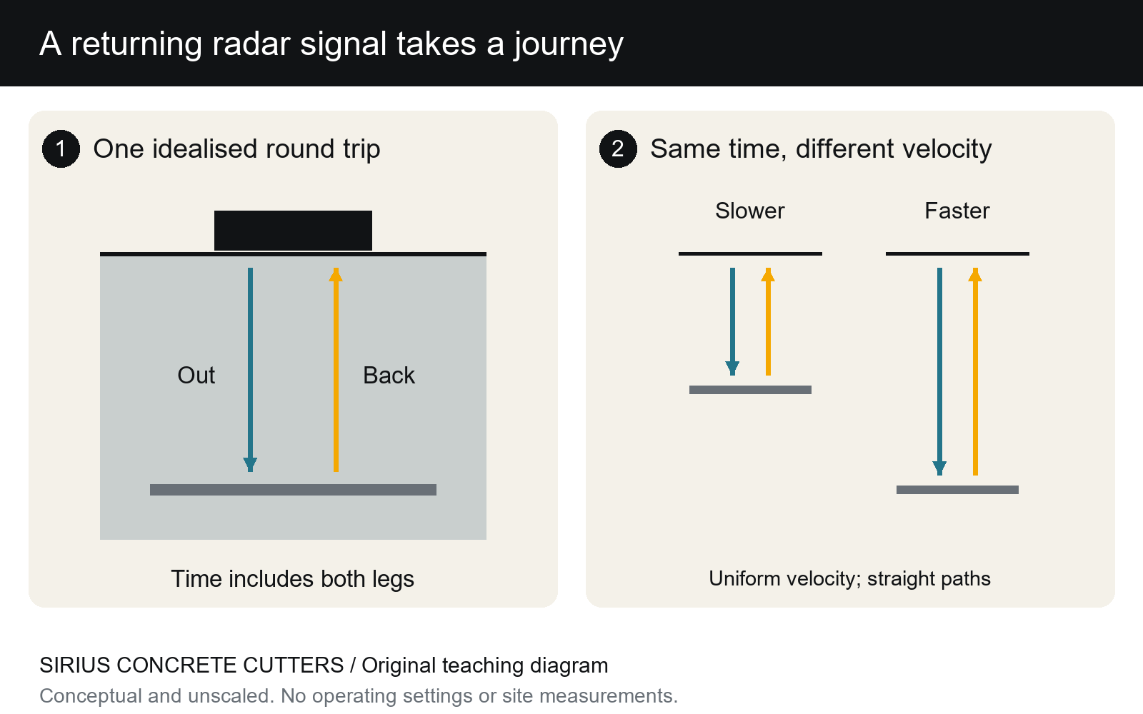
- 1. In a straight normal round trip, the signal travels to a reflector and returns: two one-way distances.
- 2. In the same total time, a faster idealised signal covers a longer path than a slower one.
- Depth = velocity × two-way time ÷ 2 applies to this simple uniform-velocity path model.
The simplest depth relationship
For a straight out-and-back path at one uniform velocity, the one-way distance is half the product of velocity and total travel time. In symbols, depth equals v times t divided by two. The assumptions are part of that statement: a defined reference, a suitable path model and an appropriate velocity. Removing those assumptions would make the equation look more universal than it is.
GSSI’s concrete handbook explains that radar measures reflection travel time and needs wave velocity to estimate depth.
Velocity belongs to the material context
Electromagnetic energy does not travel through every material at the same speed. The properties of the medium influence its propagation. Concrete is also a composite material rather than a single uniform chemical substance. A velocity assumption therefore needs an appropriate basis; it is not supplied merely by calling a surface concrete or looking at its colour.
Moisture and material differences are among the reasons that context matters in radar interpretation. It means that the time-to-depth conversion contains an assumption about how the signal travelled. A result should be understood together with the method used to establish that assumption.
A reflection needs interpretation
A returning signal is associated with a change encountered by the energy. Its appearance is not a printed label naming every object below the surface. Signal shape, position and relationships within a survey provide information for interpretation. The complete identification of a feature is a different claim from noticing a response in a recorded trace.
This distinction can be obscured by a colourful display. A bright mark may look definite because it is visually strong, but colour is part of the way information is presented. It does not remove uncertainty about the material, geometry or identity of a feature. A clear explanation should say what the evidence supports rather than allowing the display’s visual confidence to answer every question.
Real paths can be less simple
The two straight arrows in our diagram deliberately describe an idealised case. Real measurement arrangements and targets can introduce more complicated paths. An antenna moved across a surface also changes its position relative to a feature. A picture showing a single vertical journey cannot describe all those positions at once or replace interpretation of the collected data.
The same limitation applies to the word depth. Depth below which surface, at which position and to which feature? Those reference questions are needed to understand a reported distance. They show why a bare number copied from a screen loses useful meaning when separated from the survey and its interpretation.
Reading the two panels
Panel one follows one journey to a reflector and back. Panel two compares two imagined velocities over the same elapsed time. The arrows indicate direction; they are not waveforms. The drawing shows a reflector.
Scanning informs a broader decision
Sirius’s current scanning information treats investigation as an input to planning the work. A scan is not a universal statement that every concealed feature has been found, and a depth estimate is not final permission to cut. Project records, interpretation and the responsible decisions for the proposed work remain separate parts of the real situation.
For a reader trying to understand the technology, the core idea is precise and useful: the instrument records a returning signal after elapsed time. An interpreted depth additionally depends on how far that signal travelled per unit of time and what path it followed. Keeping the journey, velocity and interpretation visible prevents one attractive number from being asked to prove more than it can.
Sources and further reading
GSSI concrete handbook (2017), radar travel-time explanation.
Sirius Concrete Cutters’ current service information.
Related reading: Why concrete is a composite rather than one uniform substance and Kerf width, cut depth and blade diameter describe different things.
Sirius Concrete Cutters provides concrete scanning on the Gold Coast and in Brisbane. Get in touch to discuss your project.