
Why can a circular blade reach different endpoints on two faces?
A circular blade has a curved boundary. Where that boundary passes through material of finite thickness, its intersections with the near and far faces can lie at different positions along the cut. A line that reaches a marked corner on one face therefore does not, by itself, describe the corner through the full thickness. This geometric issue helps explain overcutting.
Sirius Concrete Cutters · 18 October 2026
For related work, see Sirius Concrete Cutters’ wall sawing service.
A rectangular opening looks simple in a front-view drawing: four straight lines meet at four corners. The cutting tool, however, may have a circular blade. The meeting between that curved tool and a thick wall creates a three-dimensional question that a flat outline can hide.
The useful idea is that the visible line on one face is only part of the cut. To understand the end of that line, imagine looking through the material from the side. The curved boundary then becomes easier to see, along with the reason two faces need not show identical endpoints.
A circle meets different depths at different positions
Start with a circle drawn beside a rectangular strip representing material thickness. In our simplified example, the circle’s centre remains outside the near face and part of the circle extends into the strip. The section is taken in the plane of the circular blade, along the direction of the cut.
At the near face, the circle reaches one position along the strip. At the far face, which lies deeper into the material, it reaches another. A vertical line through one intersection does not necessarily pass through the other. That difference follows from the circle’s shape.
The straight run and its curved end are different parts
A circular blade moving along a straight path can form a long, straight kerf. That does not mean the termination of the cut is a straight line through the material’s thickness. The long sides and the end of the cut describe different parts of the resulting shape.
Imagine sliding a round shape across a shaded strip on paper. Behind it, the swept region develops a long boundary parallel to its travel. At the stopping position, the round shape still gives the end of that region a curve. Extending the straight run does not turn the circle itself into a square.
The distinction is easy to miss in a photograph taken directly at the near face. That photograph may show a tidy straight line ending at a mark. It does not automatically show the deepest part of the cut or the shape where the cut reaches the opposite face.
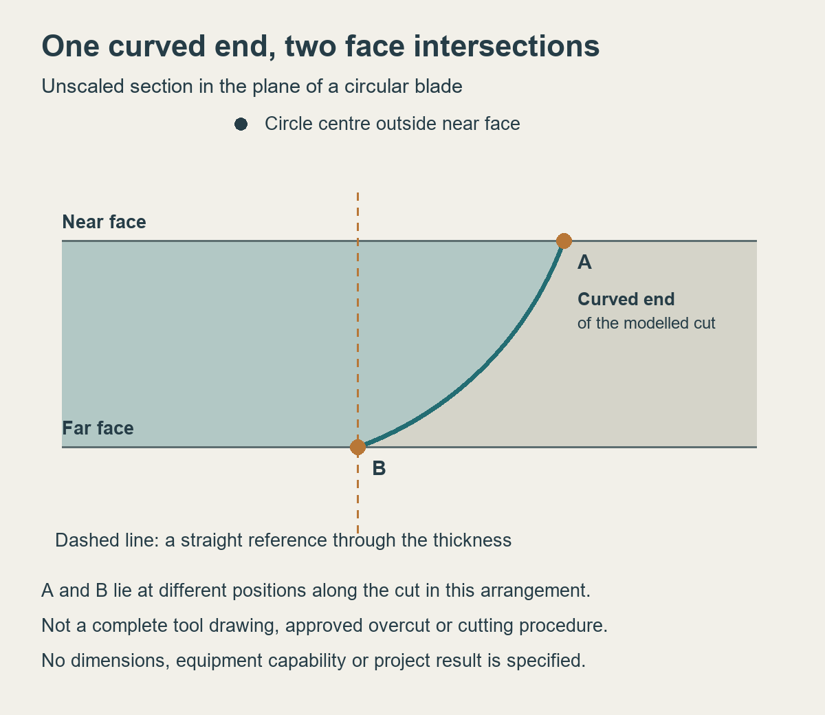
- The shaded strip represents material thickness. The curved boundary represents the end of an idealised cut in the stated outside-centre arrangement.
- A and B are the intersections at the near and far faces. They lie at different positions along the cut in this example.
- The dashed line is a straight reference through the thickness. The section shows the two faces through the material.
Why the two faces tell different stories
In the illustrated arrangement, the curved end reaches farther along the near face than along the far face. A front view and a back view would consequently show different endpoints even though both belong to the same cut.
Suppose a desired corner is represented by one line through the thickness. If the near-face intersection alone is aligned with that reference, the deeper intersection in this example remains short of it. If the deeper intersection is aligned with the reference instead, the near-face intersection lies beyond it.
The example helps explain the word overcut: part of a cut can extend beyond an intended boundary. Whether an extension is permitted, how it is assessed and how a particular corner is completed are separate project questions.
Overcut length is not one universal number
The circular geometry changes when the circle and the material thickness change. Keeping a drawing’s outline while changing one of those dimensions changes where the intersections occur. It is therefore unreasonable to treat every circular cut as having the same extension at its end.
Husqvarna’s WSC 40 operator’s manual, edition dated 22 October 2025, includes a product-context table showing that overcutting differs with surface thickness and blade dimension.
A blade’s diameter and the corner detail are separate descriptions
Blade diameter describes the circle across the tool’s centre. Material thickness describes the distance through the workpiece. A proposed opening describes the boundary that the completed work is intended to have. Those measurements belong to different objects.
Knowing the diameter does not establish the permitted corner condition. Likewise, knowing that an opening should be rectangular does not identify which tool or sequence can produce its corners in the actual material. Tool geometry helps explain the issue; it does not settle the whole method.
This is related to, but distinct from, kerf width. Kerf width runs across the narrow slot. The front-to-back endpoint difference described here concerns the termination along the cut through the material’s thickness. A narrow kerf can still have a curved termination.
Turning the sheet over does not remove the thickness
A helpful paper exercise is to imagine two transparent sheets separated by a gap. The sheets represent the near and far faces. A circular outline passes through both. Looking only at the first sheet hides where the same outline intersects the second.
Now imagine drawing the intended corner at the same location on both sheets. The reference is straight through the gap, while the circle remains curved. This makes the missing information visible without relying on a particular cutting machine or an exaggerated photograph.
The exercise does not model the strength of concrete, reinforcement or the behaviour of a separated section. Its purpose is narrower: two aligned marks on opposite faces and a curved tool boundary are different geometrical descriptions.
A different cutting shape can address a different detail
A circular disc is one working shape among several used in concrete cutting. Diamond chain equipment has a different working outline around a guide bar. Changing the working shape changes the geometry available for a corner detail; it does not remove every material or site constraint.
The WSC 40 manual describes its product’s intended corner-cutting role without overcutting. That manufacturer-specific example helps show why a corner can be a distinct part of the method discussion.
Sirius’s concrete chainsaw service information and wall-sawing service information provide relevant service context.
The desired opening is more than its front outline
For an opening through thick material, a front outline describes only one face. The finished boundary extends through the thickness, and the surrounding retained material also matters. A photograph of the front can be accurate while remaining incomplete as a description of that volume.
This is similar to looking at the mouth of a tunnel without seeing its path. The entrance has a visible boundary, but that view alone does not describe every surface farther inside.
Concrete also contains material that a simple outline does not identify. Reinforcement, services and the structural role of the surrounding element are not established by a circle-and-rectangle diagram.
Reading the view prevents the wrong comparison
A plan or front elevation can make the cut appear as a line. A section in the blade plane can show the curved termination. A section across the slot can show its width. Each view is useful because it answers a different spatial question.
Before comparing two apparent endpoints, identify which faces they belong to. Before comparing a blade dimension with an opening dimension, identify which objects are being measured. This small distinction prevents a precise-looking number from being attached to the wrong feature.
The useful lesson is in the section
The stated arrangement matters. In our drawing, the two faces lie at different distances from a circle centre outside the material. That is the reason their intersections on the illustrated side occur at different positions. The drawing does not claim that any two parallel lines through any circle must produce unequal intersections.
For example, two imaginary parallel lines placed equally far on opposite sides of a circle’s centre would meet a symmetrical circle differently from the arrangement shown here. It explains why identifying the model’s arrangement is part of understanding its conclusion.
The same care applies when a diagram is simplified. Omitting equipment makes the curve easier to see, but it also removes information needed to assess a real setup. A useful teaching model states both its arrangement and its purpose. It can explain why an endpoint difference occurs.
A circular blade can create a straight run while leaving a curved end through the material’s thickness. The intersections of that curve with two faces can occupy different positions. That is why reaching a visible mark on one face does not necessarily describe the corner on the other.
Seeing the section turns an apparently puzzling corner into understandable geometry. It explains the tool and the shape of a cut.
Sirius Concrete Cutters serves the Gold Coast as its primary market, with Brisbane secondary.
Related reading: Kerf width, cut depth and blade diameter describe different things and Why a diamond blade has a supporting core and a working rim.
Sirius Concrete Cutters provides wall sawing on the Gold Coast and in Brisbane. Get in touch to discuss your project.